IECEx: Meaning and Requirements

IECEx: Meaning and Requirements

IECEx: MEANING AND REQUIREMENTS
IECEx is an international certificate for electrical equipment used in explosive atmospheres (Ex equipment) intended to facilitate global trade in electrical equipment for use in hazardous locations, while maintaining the required safety.
Where is Ex Equipment Typically Found?
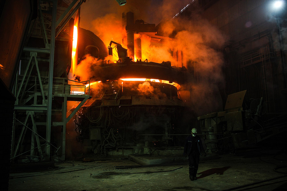
Ex equipment is commonly found in the following industrial environments:
- Automotive refueling stations or petrol stations
- Oil refineries, rigs and processing plants
- Chemical processing plants
- Printing industries, paper and textiles
- Hospital operating theaters
- Aircraft refueling and hangars
- Surface coating industries
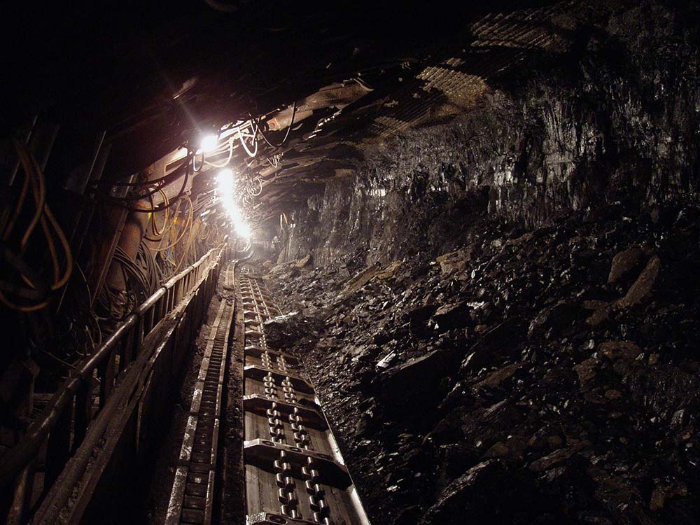
- Underground coal mines
- Sewerage treatment plants
- Gas pipelines and distribution centers
- Grain handling and storage
- Woodworking areas
- Sugar refineries
- Metal surface grinding, especially aluminum dusts and particles
(list courtesy of IECEx.com)

Where is IECEx Accepted?
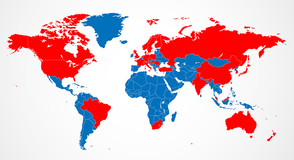
The following countries accept the IECEx certifications:
(please note that this list may be subject to change)
- Australia
- Brazil
- Canada
- China
- Croatia
- Czech Republic
- Denmark
- Finland
- France
- Germany
- Hungary
- India
- Italy
- Japan
- Korea
- Malaysia
- Netherlands
- New Zealand
- Norway
- Poland
- Romania
- Russia
- Singapore
- Slovenia
- South Africa
- Sweden
- Switzerland
- Turkey
- United Kingdom
- USA

map image designed by Freepik
Guidelines for Use & Installation
- A barrier is required for the installation of IS sensors. The barrier passes signals in either direction as required, but limits the voltage and current that can reach the hazardous area under fault conditions. The barrier is put in series and is installed in a safe area.
- Proper IS barrier must be used with this sensor to ensure compliance with entity parameters.
- Approved cabling (maximum 200 ft / 60 m) must be used to bring the signal from the sensor to the Zener diode barrier or galvanic isolator, which is the energy-limiting interface.
- Sensors must be grounded to a grounded structure by stud mounting the sensor directly to the machine surface, ensuring metal (of the sensor) to metal (of the machine surface) contact.

Entity Parameters
| Model | Description | Vmax | Ci | Imax | Li | Pi |
| AC95X Series | Accelerometer | 28 V | 70 nF | 100 mA | 51 µH | 1 W |
| AC96X Series | Accelerometer | 28 V | 0 nF | 100 mA | 0 µH | 1 W |
| LP852 Series | Loop Powered 4-20 mA Output Sensor, Velocity | 28V | 70 nF | 100 mA | 51 µH | 1 W |
| LP862 Series | Loop Powered 4-20 mA Output Sensor, Velocity | 28 V | 0 nF | 100 mA | 0 µH | 1 W |
| LP952 Series | Loop Powered 4-20 mA Output Sensor, Velocity | 28 V | 70 nF | 100 mA | 51 µH | 1 W |
| LP962 Series | Loop Powered 4-20 mA Output Sensor, Velocity | 28 V | 0 nF | 100 mA | 0 µH | 1 W |
Vmax = Maximum Voltage
Ci = Total Capacitance of Circuit Allowable
Imax = Maximum Allowable Current
Li = Total Inductance of Circuit Allowable
Pi = Total Power of Circuit Allowable
Note: IS111 and IS211 barriers are compatible with AC95X, AC96X, LP852, LP952, LP862 and LP962 series sensors.
Accessories
CTC offers a variety of the world most durable and reliable cabling options.
CB102 – twisted, shielded pair cable, red FEP jacket, .175″ OD, 392°F:
![]()
CB103 – twisted, shielded pair, black polyurethane jacketed cable, .245″ OD, 250°F:
CB111 – twisted, shielded pair cable, yellow FEP jacket, .190″ OD, 392°F:

CB193– twisted, shielded pair, RAL blue polyurethane jacketed cable, .175″, 250°F:

CB206 – twisted, shielded pair, stainless steel armor, red FEP cable, .270″ (6.9 mm) OD, 392°F (200°C):
![]()
Note: the standard cable for integrated applications is CB103 polyurethane jacketed, twisted, shielded pair cable.

